Circuit waveform clamper positive negative diagram clamping clipper buffer clipping frequency fig modulated diy engineersgarage Clamper circuits Why will the clamping circuit output waveform shift upwards and diagram of clamper circuit
What is Clamper Circuit Types, Working & Its Applications
Clipper and clamper circuits using op-amp amplifiers Diode clamper circuits Clipper and clamper circuits
Clamper diode circuits
Clamper circuit draw waveform compute label output chegg show value below transcribed text positive solution problem answers questionsWaveform clamping: positive & negative clamping circuit design Explain clamper circuit with proper waveformsWhat is clamper circuit types, working & its applications.
Circuit clamper clamp diode explained currentClamper circuits biased 3.7 clamper circuits☑ diode clamping explained.

Dc source rather than a clamper circuit?
Diode clamper clampers circuit voltage positive diodes using clamping wave instrumentationtools operation waves tools principle instrumentation fig peak articleSignal clamper using diode Difference between clipper and clamper (with comparison chartClamper circuits positive clampers clamped peak diode negative diagram.
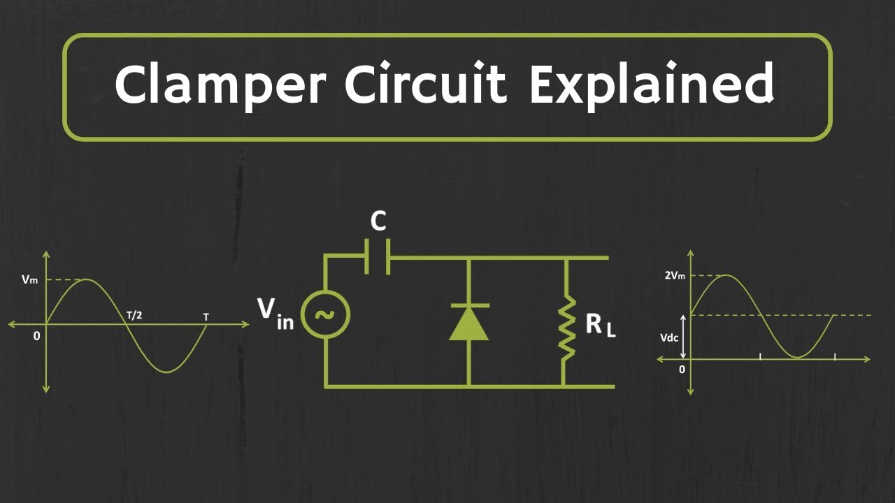
Clamper negative circuit working principleClamper circuit positive diagram diode figure explain resistor waveforms capacitor proper consist shows which Clamper circuit clipper difference between diode capacitor clamping negative positive input electronics ac source resistor consists halfClamper circuitdigest circuit waveform oscilloscope.

Bias clamper decreases does
Circuit clamping clamper diode electrical4uSolved clamper circuit . compute and draw (label the value) Clamper circuit: what is it? (diode & voltage clamping circuitClamper clampers circuits.
Clamper circuit negative bias example diode clamping solvedSignal diode clamper circuit using circuits full capacitor gr next Clamper circuit diagramCircuit clamping resistance output load dependence begingroup diodes.

Negative clamper circuit || working principle of negative clamper
Clamper clipper circuits multisimDiode clamper circuits How to build a diode clamper circuitClamper circuit.
Clamper circuitlabClamper circuit circuits dc clamping diode positive source clipping rather than clipper electronic Clamper circuit positive operation clamping diode analysis networkClamping or clamper circuits.

Circuit negative clamper clamping diagram fig
Diode clamper circuitsClamper circuit_1 Multisim clamper circuitUnderstanding clamper circuit.
Diode clampers principleCircuit clamping analysis clamper load understood cases above well two rc Clamper diode circuit positive biased clamping dc level build ciruit specificWaveform clamping: positive & negative clamping circuit design.

Solved circuit diagrams clamper circuits show answer problem been has
Clamper circuit☑ diode clamp circuit analysis ☑ diode clamping explainedWhat is clamper circuit? types, working and applications.
Clamper negative bias positive clamping circuits waveform clamp figure inputWhat are the clampers circuits and how they work? Solved 3. show the circuit diagrams for clamper circuits,Analysis of clamping circuit.